
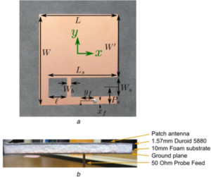
a. Top view of the PCB patch antenna prototype (CP Half E-shaped patch). b. Side view illustrating the layer stackup of the antenna.
Two things that antenna engineers do not often hear in the same sentence: broadband and patch antennas. One of the most popular types of antennas, patch antennas, have many useful features for designers including a low-profile (they can be as thin as a few mm’s) and can be directly integrated with PCB circuits and chips. As with anything in engineering, every design comes with its drawbacks. For patch antennas, the most notorious is bandwidth, where fractional bandwidths on the order of 5% is the norm and 10% is excellent. This means that we would get roughly 100-200 MHz of bandwidth if we were operating at 2 GHz, for example. During my PhD and postdoc, I have spent considerable time investigating ways that we can surpass typical limitations without significant design complexity.
When you add circular polarization into the mix, bandwidth capabilities become even more limited. Circularly polarized antennas radiate electromagnetic fields that spin in a circle over time, giving rise to a strong signal without the need to “polarization-align” the antennas. So now we have two features that constrain our bandwidth: getting the power out efficiently and making the electromagnetic waves spin in a circle. Each of these features are difficult to pull off over a wide bandwidth by themselves. Maintaining both good efficiency (losses and mismatch) and good circularity is even more challenging over sizable bandwidths. I have recently conducted several investigations to both understand why this happens in patch antennas and potential approaches to optimize the bandwidth performance further. A previous article that I published:
J. M. Kovitz and Y. Rahmat-Samii, “Using Thick Substrates and Capacitive Probe Compensation to Enhance the Bandwidth of Traditional CP Patch Antennas,” IEEE Transactions on Antennas and Propagation, vol. 62, no. 10, pp. 4970-4979, October 2014.
revisited bandwidth problem for CP patch antennas and put some effort towards pinpointing exactly what physical mechanism limits their bandwidth. Furthermore, we showed that how to use simple modifications that were previously used in linearly-polarized patch antennas to increase the bandwidth of typical CP patch antennas. A major issue with the designs we proposed in this article was the manufacturability of the antenna designs (there were small gaps).
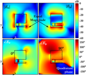
Graphical illustration of the CP operation in the CP Half E-shaped patch antenna
Continuing these efforts, I recently wrote a paper with my colleagues Harish and Yahya that describes a patch antenna design that we stumbled onto by accident. It was fairly early in my PhD that we made this discovery, but it took us a good bit of time to fully understand and characterize the design (as well as getting around to writing the paper). The article is entitled:
J. M. Kovitz, H. Rajagopalan, and Y. Rahmat-Samii, “Circularly-polarised half E-shaped patch antenna: a compact and fabrication-friendly design,” IET Microwaves, Antennas, and Propagation. vol. 10, no. 9, pp. 932-938, June 2016.
and is now available on IEEE Xplore. The focus of this article was on the possibility of a broadband CP patch antenna that could be more easily manufactured compared to existing technologies. For those that are familiar with PCB manufacturing, the antenna only requires a single metallic layer etching, and only one coaxial input is required to excite the antenna. The prototype can be seen in the figure at the beginning of this post. If you are wondering where the “E” is from the name “E-shaped”, it is a bit of a long story that starts with another article by a previous student. The short story is that we inherited the name because we were working on the E-shaped patch (which really does look like an E-shaped patch) and the design evolved to this miniaturized version.
Overall, the paper is very interesting, and I talk about the operation of the CP Half E-shaped patch antenna compared to other variations of the E-shaped patch. The exotic shape of this antenna made it a bit difficult to analyze, but we used a lot of graphical evaluation tools that help justify our conclusions about its performance. The graphic on the right shows equivalent magnetic currents which allow us to visualize the radiation that contributes to the CP feature. Potentially the most exciting aspect of this new design is that the CP Half E-shaped patch can be nicely inserted into planar arrays (previous CP E-shaped patch antennas were too large). In fact, we are close to publishing another article about how you can use this design in future Mars Rover antennas.